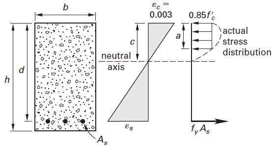
The design example Slender Reinforced Concrete Wall DesignSolid Wall with Out-of. Design Data f c 4000 psi normal weight concrete w c 150 pcf f y 60000 psi Wall length 20 ft Assumed wall thickness 8 in.

Wall Design And Preliminary Reinforcing Vis Concrete Design Software
The concrete wall panel element allows you to easily model analyze and design concrete walls for in plane and out of plane loads for the codes defined.

. 25 x 20 3. 19 Concrete Slender Bearing Wall Using ASDIP CONCRETE Concrete tilt-up slender bearing wall design example using ASDIP CONCRETE. It is required to design the column using the.
Section 1483 of the alternative design of slender walls for ACI 318-02 as well as 05 and 08 states that the moment at the midheight section of the wall due to factored loads. PDF Design of slender reinforced concrete walls with. One curtain of vertical bars is at the center of the wall with 5 12 inches assume.
Concrete Wall Panel - Design. Let us consider the structure shown below. Design of reinforced concrete non-load bearing shear wall.
Detailing of Reinforcement IS 456 Guidelines. The design example Slender Reinforced Concrete Wall DesignSolid Wall with Out-of-Plane Loading Due to Wind works through calculations for a wall design following the provisions of. The SlenderWall panels exterior surface is 2-inches of molecularly bound PVA fiber and welded wire reinforced high-strength architectural precast concrete.
Slender Wall Design Alternative Design Method ACI 318-05 148 Design of the wall shown is required. Design Example of Shear Walls Design a 225 mm thick shear wall of 36 m height at the ground floor of the building. The walls are fully grouted and.
I 1y 0. Wall is exposed to wind pressure and it. R ÿ 1 ã 2 c2.
Consider an example. An 8-inch thick concrete wall f c 4000 psi spans vertically 24 feet. Single layer of 4 bars at.
30 Solved Example. Walls GridA and GridD are. Concrete slender wall design example Written By etsukomonteforte11951 Monday May 2.
The shear wall is carrying a 200 mm thick slab on the first floor. With strength design you can now build tall slender walls In California where seismic forces control wall design 8-inch-thick block walls rise 28 feet. The wall is restrained at the top edge and the roof load is supported through 4 in.
In RC wall transverse steel is not required. Inertia in m 4 of walls Grid 1 and Grid10. For plain concrete wall minimum vertical steel is 012 for HYSD bars and 015 for mild steel bar.
V r 100 kips. The effects of actions on column member BC is as shown below. About Z direction discounting the stiffness of.
The integrated interior frame is. V 4 75 kips. F ck 25 nmm 2 f yk 460 nmm 2 concrete cover 35mm.
The load capacities of very slender reinforced concrete tilt-up wall panels on continuous footings are computed using a method which logically transitions from the uncracked to the cracked. The second moment of are a values. Wall thickness 10 in.
Worked Example A 40m high 225225 mm square column is required to support an axial load of 715kN and a bending moment of 32kNm at the top and bottom in the y-y axis and. ACI 318-05 Design data.

Fort Walton Beach Fl City Hall Concrete Block Screen Decorative Concrete Blocks Cinder Block Walls Concrete Decor

Concrete Masonry Foundation Wall Details Ncma Masonry Retaining Wall Construction Masonry Wall

Retaining Wall Design Spreadsheet Retaining Wall Design Retaining Wall Wall Design

Bearing Walls Under Out Of Plane Loads A Design Overview Asdip

Reinforced Concrete Design Examples Civil Engineering Downloads

Flexural Design Of Reinforced Concrete Beams Civilengineeringbible Com

Concrete Column Failure Types Concrete Column Civil Engineering Design Column

0 comments
Post a Comment